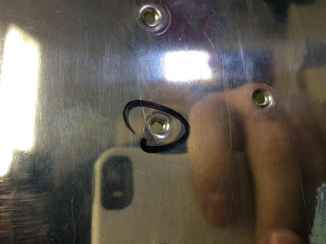
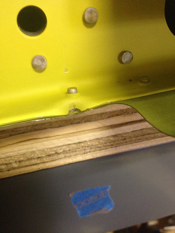
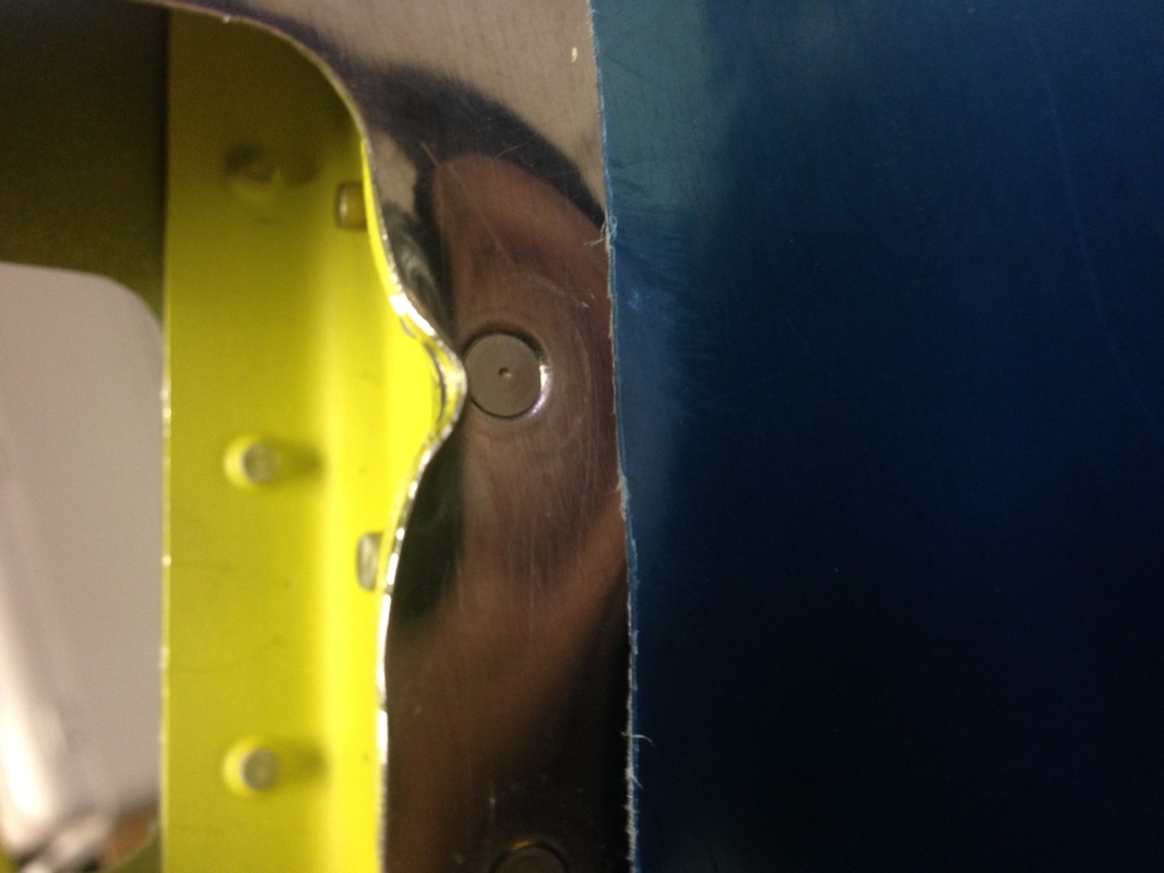
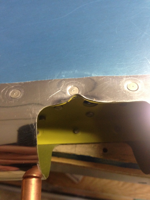
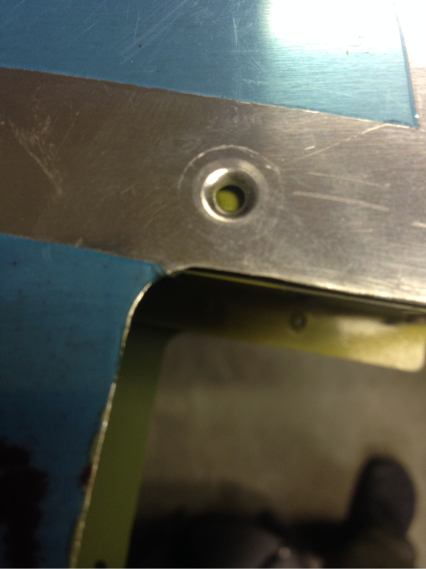
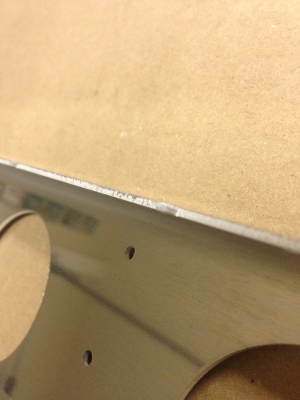
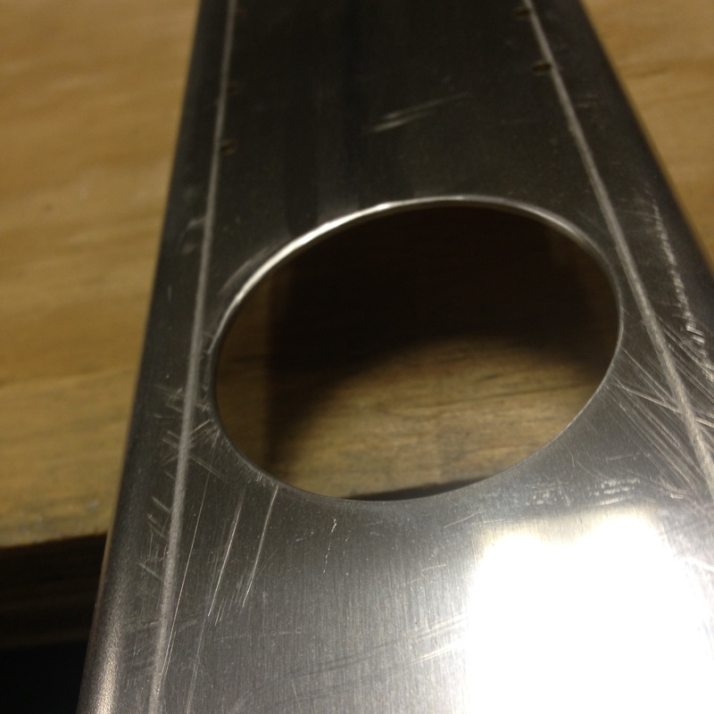
I'm disappointed I didn't get any pictures dimpling the HS skin since it was such a pain! I did however have a oops moment when I made a figure 8 hole. I've seen much worse on VAF so I wasn't too concerned. It was more like an elongated hole rather than a true figure 8. My fix was to upsize the hole for a #4 rivet which seemed to work out perfectly. We'll see for sure when I get around to riveting it. 
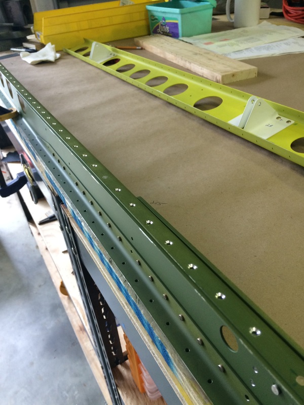
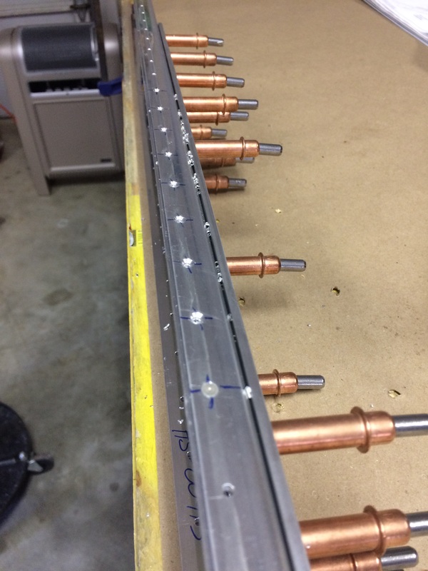
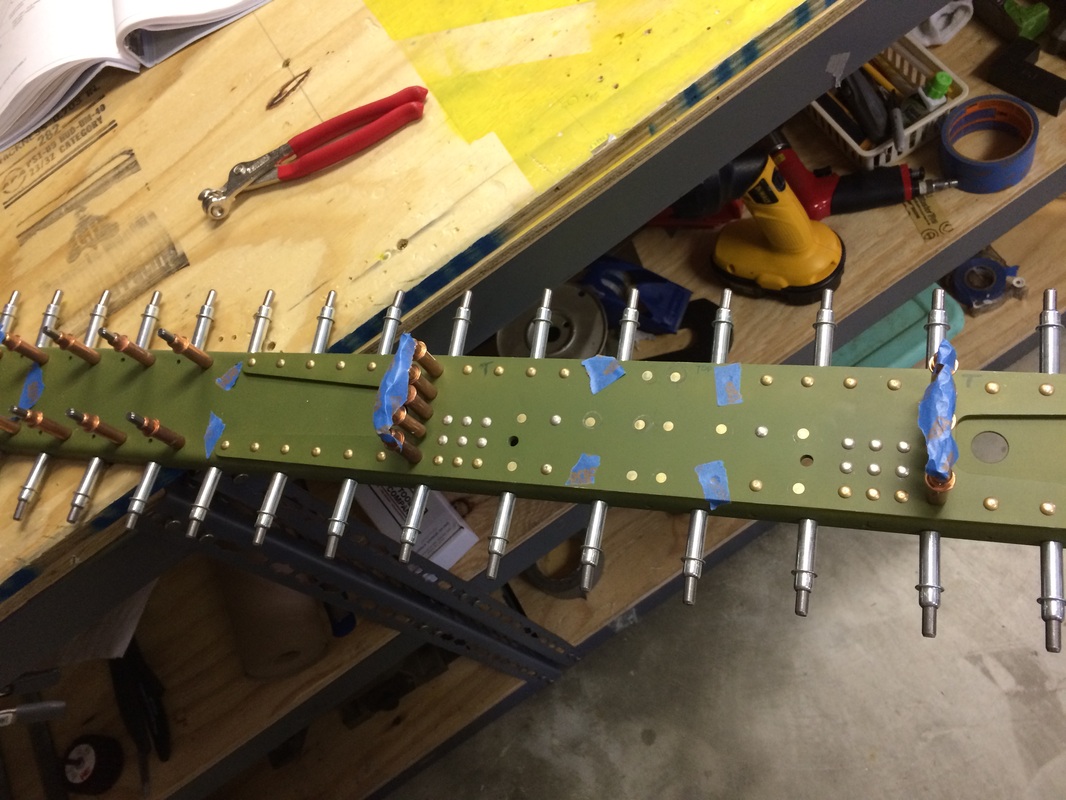
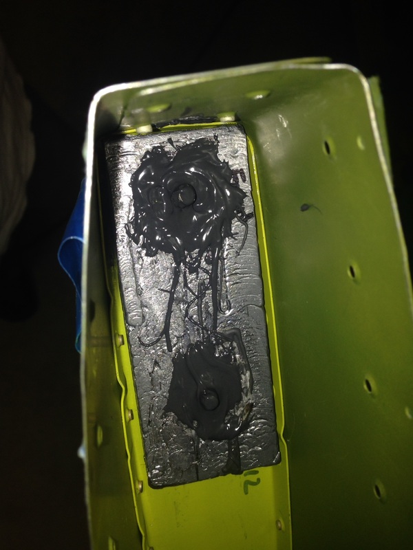
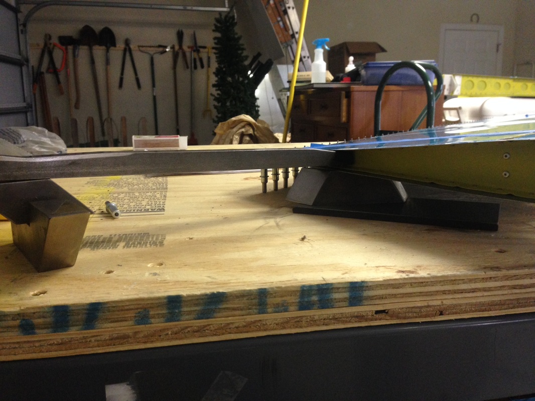
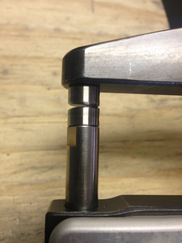
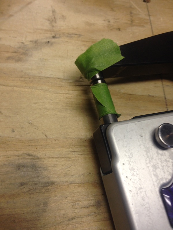
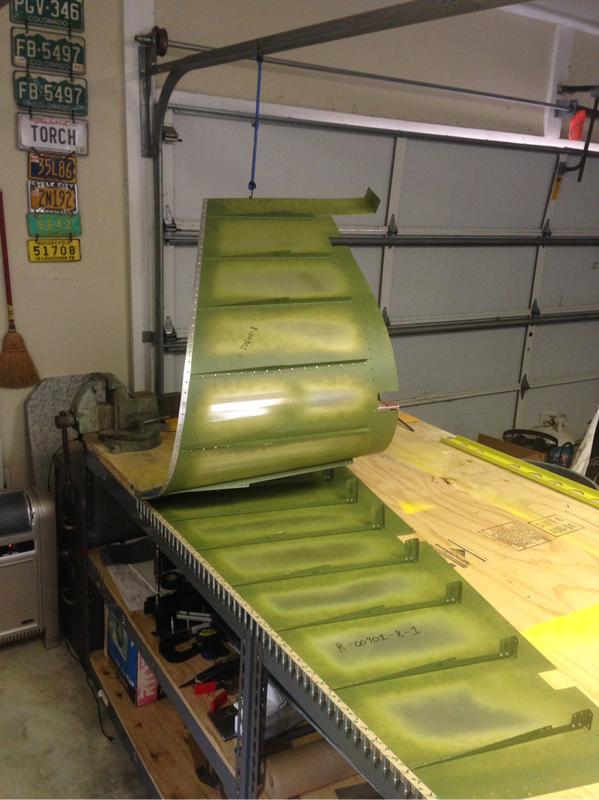
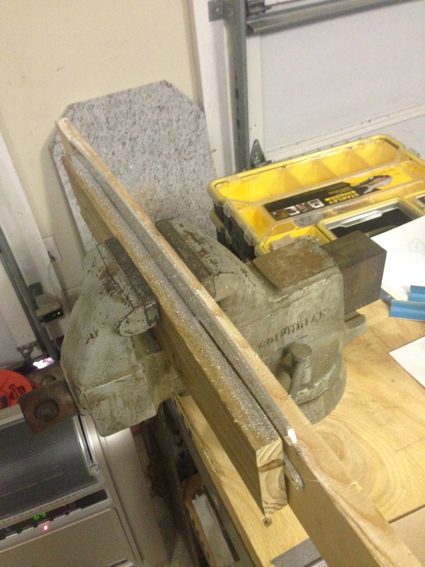
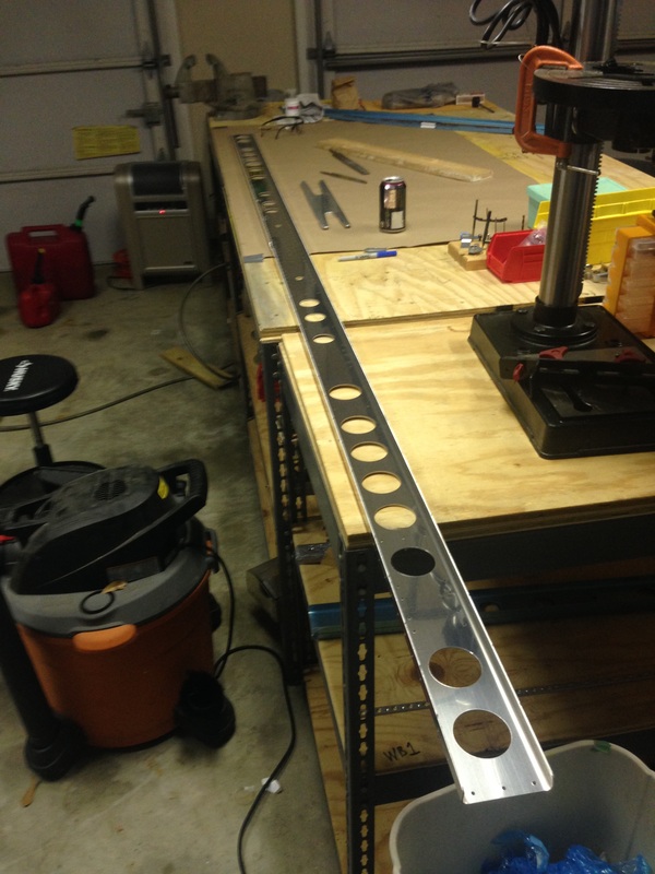
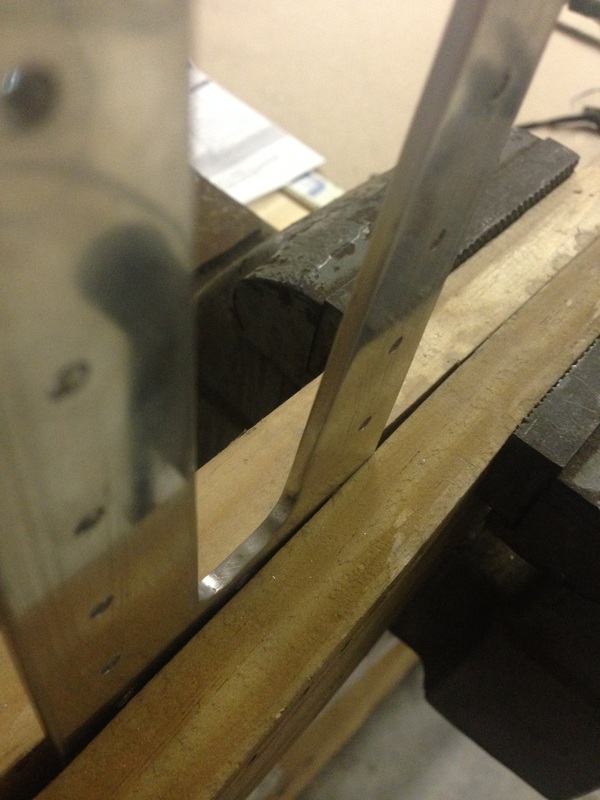
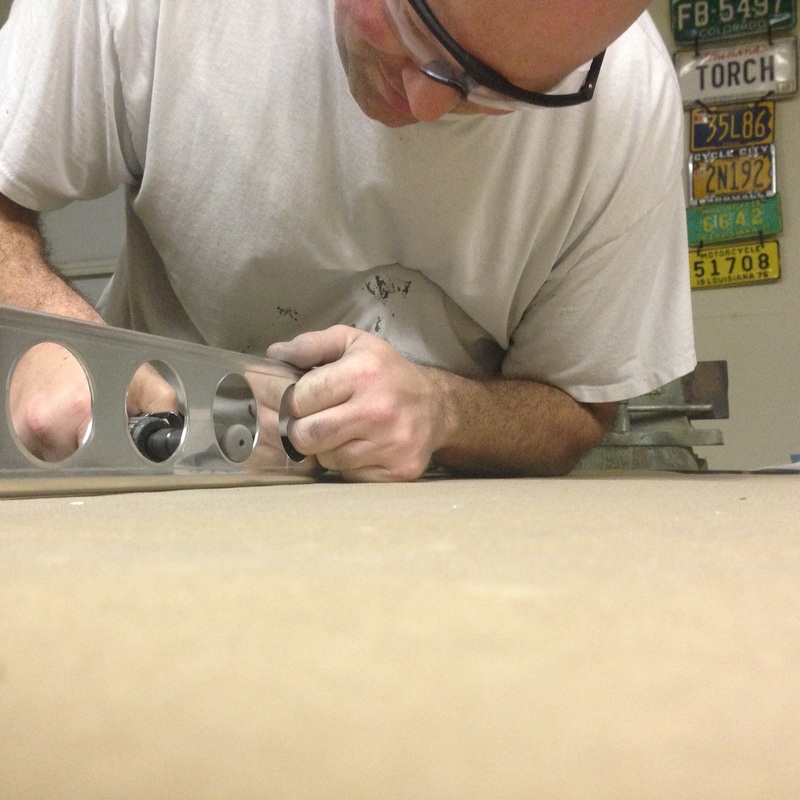
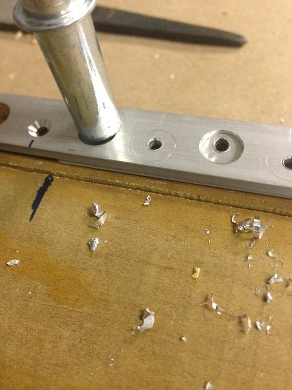
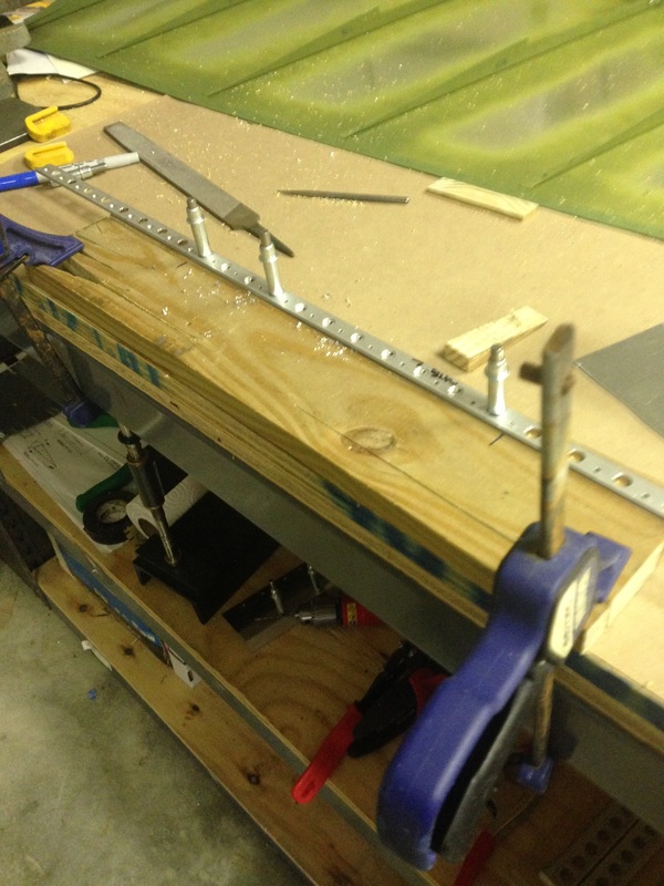
After I finished dimpling I thought it was time to start putting parts together. Man was I wrong! I forgot that the spar had to be countersunk. It didn't take near as long as I was anticipating. 
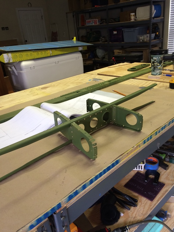
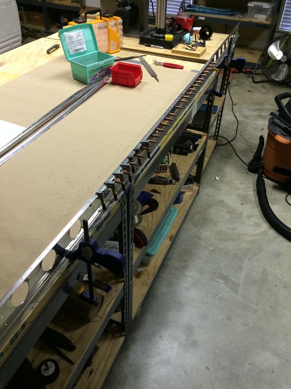
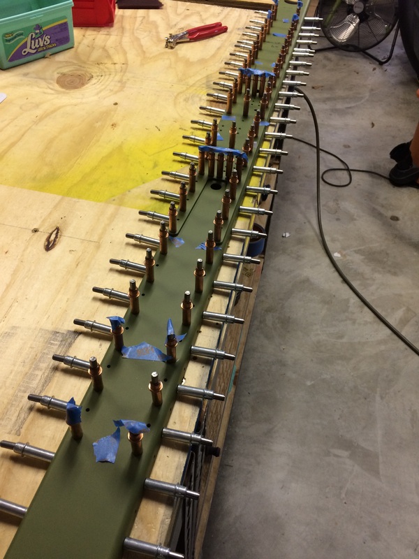
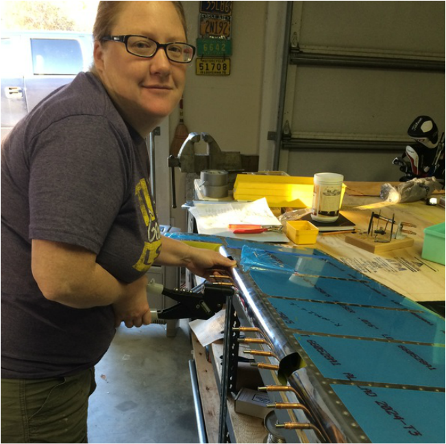
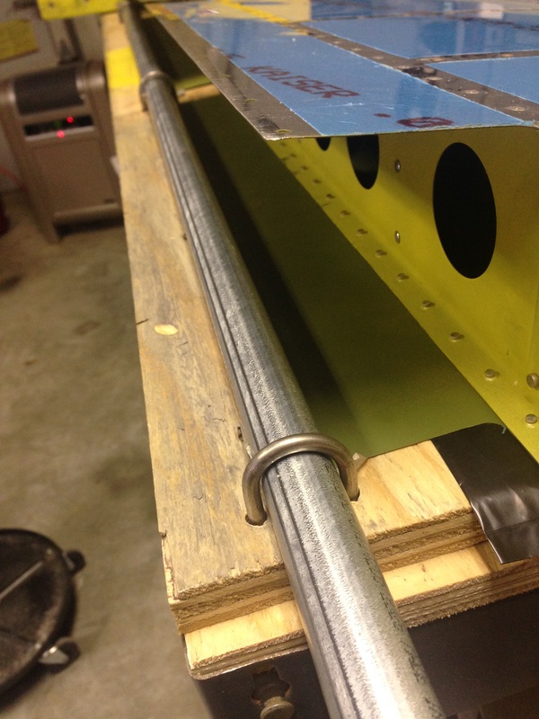
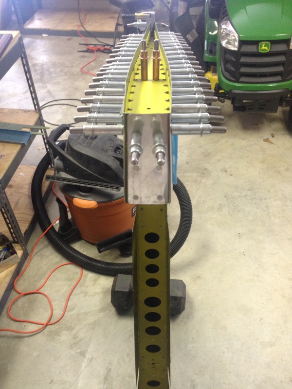
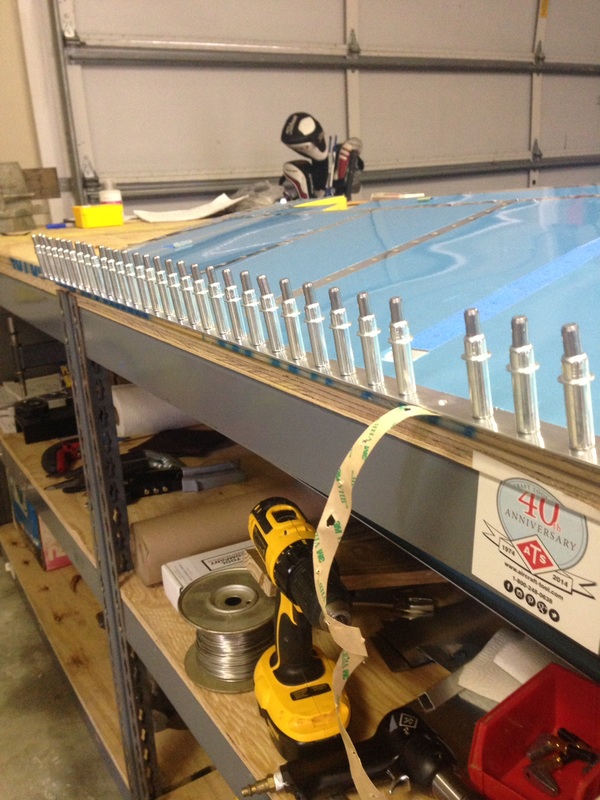
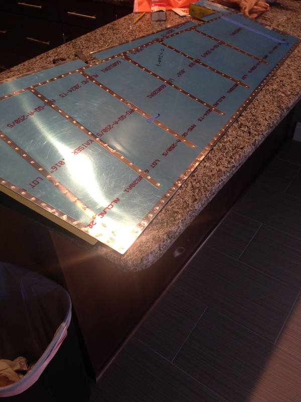
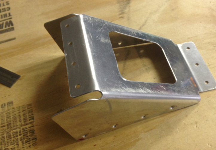
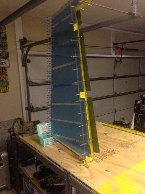
I wrapped up the day putting together the center section of the HS.
0 Comments
I had a few hours this evening so I built the cradles called for in the plans. The shipping crate came in handy here.
After some ~6 hours of prep work its finally time to set the first rivets on the HS. I was sure to take my time and work very methodically through these rivets by highlighting in the plans what rivets I have completed. At this point the plans only show half of the HS because the other half is mirrored and follows the same rivet pattern. The blue tape reminds me where I am not to rivet.
After the factory and VAF talked me off the ledge and let me know that the ding was not the end of the world I brought the rudder to an A&P buddy. Less than five minutes later the problem was solved. It doesn't look as good as new but paint and filler will cover everything up just fine. When I got home that evening, I had Tiffany help me put the finishing touches on the rudder by riveting the skins together.
The previous day's success in finishing up the trailing edge had me enter the "factory" with enthusiasm the next morning to finish up the rudder by rolling and riveting the leading edge. Again, I consulted many different blogs to determine the best method to roll the edge. I ended up putting 3 U Bolts through my table to hold a 3/4" piece of conduit down which I could then turn with a pipe wrench. The first roll went as planned. As I was peeling the tape off of the other side my heart sank when I saw the gouge that the U Bolt left in the spar and skin. I must've been lucky on the first roll because the top section completes its roll before the 2 lower sections. I rolled too far and that's why the U Bolt dug in. To add salt to the wound, the edges went together beautifully! I was done for the day.
After some asking around, the consensus was to heat up the JB Weld to chip it off. I broke out my heat gun and did just that. The whole thing ended up being a total non event, just a few more hours added to build log. Now it was time to button the top up by adding the last rib. I was a little worried because the skin at the top was very bunched up in areas and didn't lay flat. Once the rib was installed it fit like a glove. Driving the aft most rivet on the rib took a little thinking. I quickly remembered doing this on the practice project. However this far into the build of "real parts" brought the pucker factor up. I switched to my 3x gun and turned the air up and hit in very, very, short bursts, re-positioning the bucking bar rig before every trigger squeeze. Now it was time for the dreaded trailing edge...I decided to follow the plans and use the 3M tape instead of the pro seal, jb weld, 5200, etc... As it turns out, Van's suggested the 3M tape for a reason: It was simple, AND it works! The bond along the trailing edge is tight except for the ends that come apart a little (I have a few ideas to fix that). I did however deviate from the plans and did not back rivet the trailing edge. I read a few different build sites and decided to start by barely setting the rivets (every 10th as per plans) just until the shop heads got close to the skin. Next I switched out to the modified dies from Avery and squeezed slowly until just flush. On a few of the rivets I stopped slightly proud of flush because I could see the skin would be distorted if I went any further. This process worked well and the finishing results were 1/4" twist when the difference of both sides were measured. I'm satisfied.
After this mistake I have decided to take a break from the project because I am having too many mental mistakes. At this point I have just over 66 "Shop Hours" logged in less than a month of building. I definitely expect the hours towards the project to drop off drastically anyway because I had quite a bit of time off from work last month.
Anyway... I ended up securing the counterweight for the rudder per the plans except I added JB Weld to the locknut for added security as this area will be inaccessible after everything is buttoned up. Low and behold I forgot to rivet AND dimple the forward flange and skin of the rudder where it meets the counterweight rib. Getting the JB Weld off wasn't too bad using the heat gun and slowly chipping away at it. I have decided to replace both the locknut and the screw for piece of mind. This is the replacement R-00910 horn brace that I messed up a few weeks ago. With the holidays it took two weeks to receive this from Van's. The manual has you get a helper to roll back the skin so you can pop rivet the stiffeners. Tiffany worked last night and was sleeping so I figured out a way to do it solo. It actually was pretty painless and worked out well. I remembered at the last minute that only the forward hole of the aft two gets a rivet the other hole remains empty. I'm sure it would not hurt if I had done both of them but I've seen several posts on VAF saying the aft most hole was only there to cleco. ![]() For whatever reason I could not both L and R skins to line up properly when I had the rudder on its side. It's hard to tell in the picture but the bottom side is perfect but clearly the top isn't even close to lining up. I ended up standing the rudder vertically and magically the skins lined up. I started in the middle of the spar and worked my way back and forth outward until it was all lined up. Next I riveted the shear clips to the spar.
At this point I'm at a stand still with the rudder since I'm still waiting for the replacement horn from Van's. So why not start the horizontal stabilizer? Much like the other couple of sections, the CNC cut parts have extremely rough edge and need alot of attention. The fruits of my labor.
I spent about 4 hours on the trailing edge countersinking both sides. I didn't like my drill press set up so I ended up match drilling the strip to a piece of scrap so the pilot of the CS cutter would have something to guide it. I then took a scrap piece of trailing edge strip and stuck it underneath the piece I was drilling and clecoed the whole sandwich to the scrap. I chucked the CS cage in my cordless drill and proceeded SLOWLY by cutting a little at a time constantly rechecking with a flush rivet. I read on VAF to that you should CS slightly below flush which means going deep enough to see a small ring around the flush rivet. I know the process wasn't the most efficient, but it worked.
|
Categories
All
Archives
March 2016
|