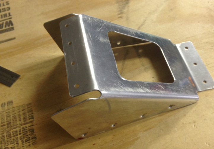
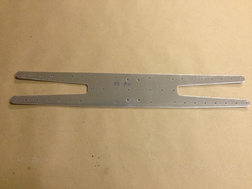
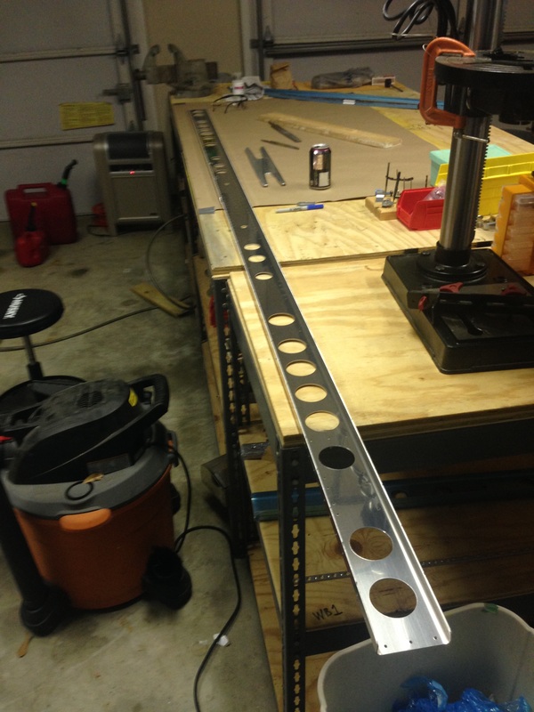
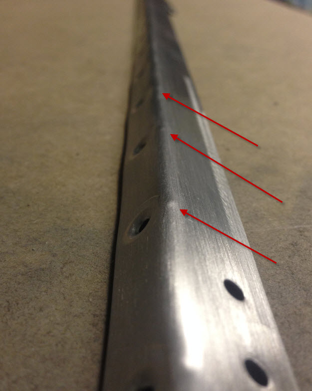
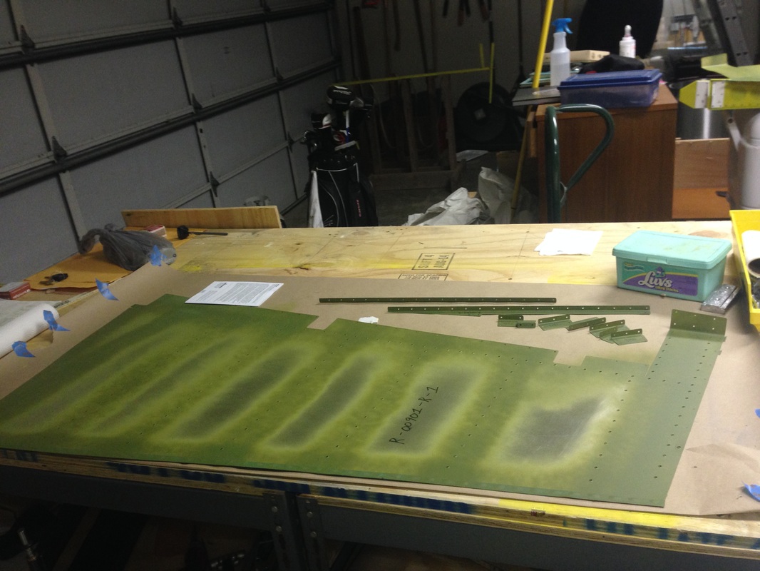
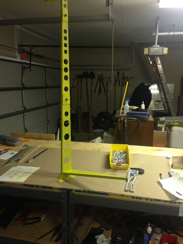
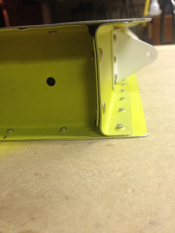
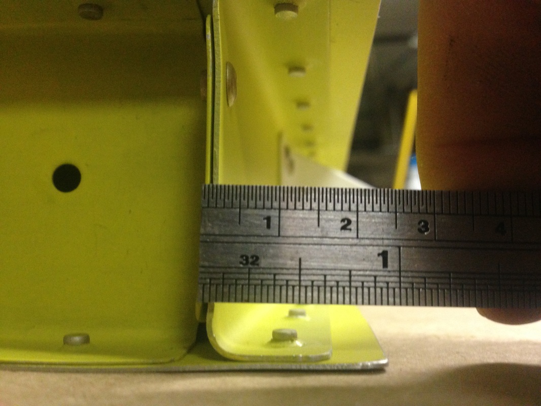
This is the replacement R-00910 horn brace that I messed up a few weeks ago. With the holidays it took two weeks to receive this from Van's. 
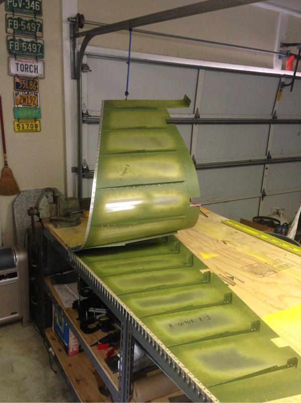
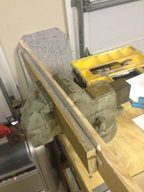
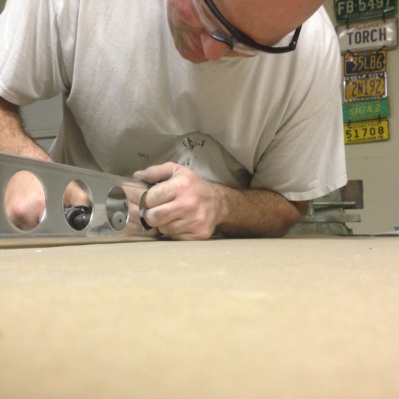
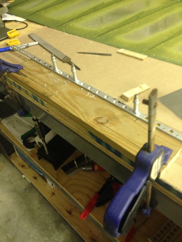
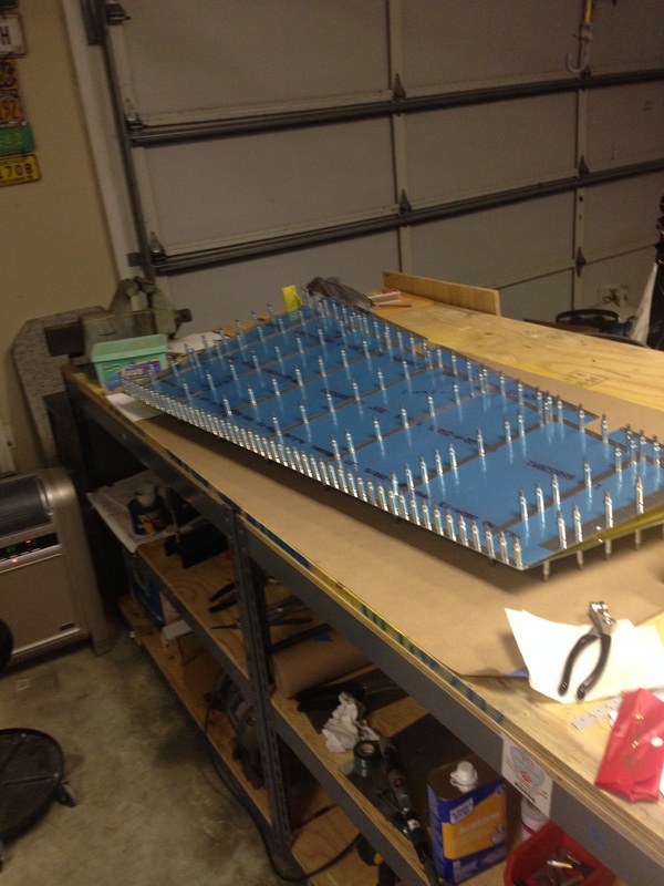
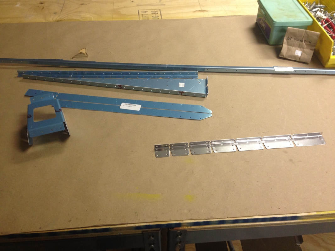
The manual has you get a helper to roll back the skin so you can pop rivet the stiffeners. Tiffany worked last night and was sleeping so I figured out a way to do it solo. It actually was pretty painless and worked out well. 
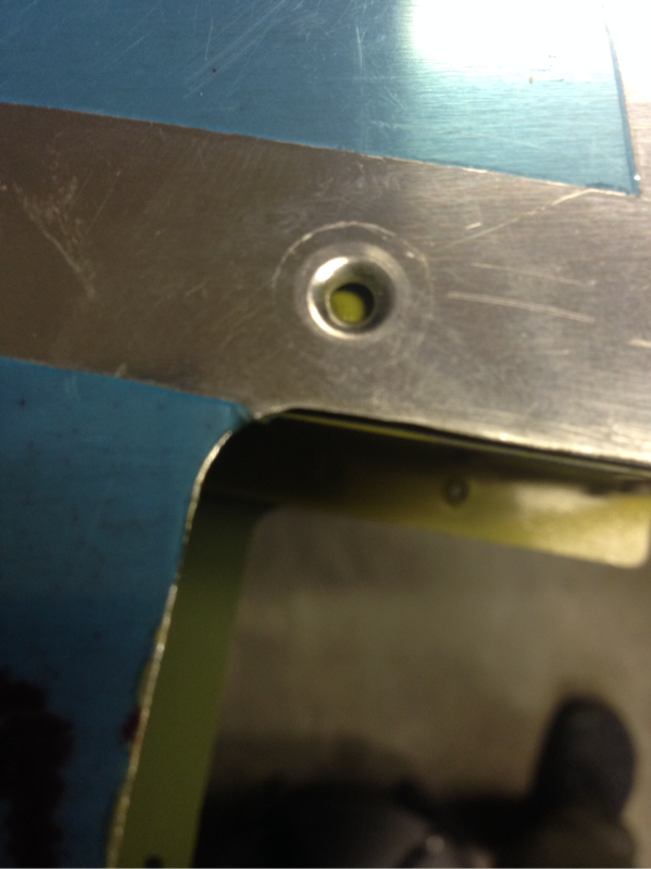
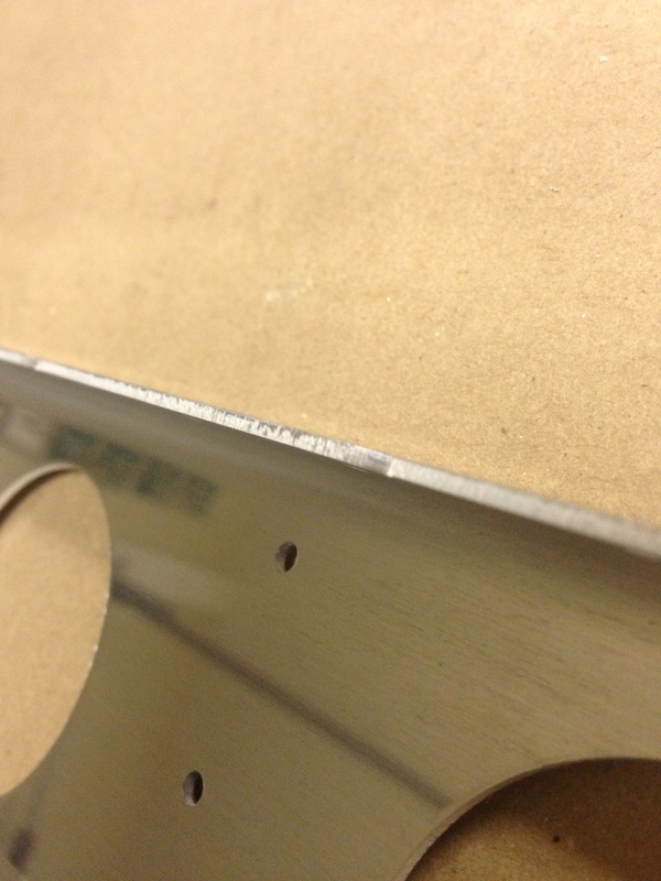
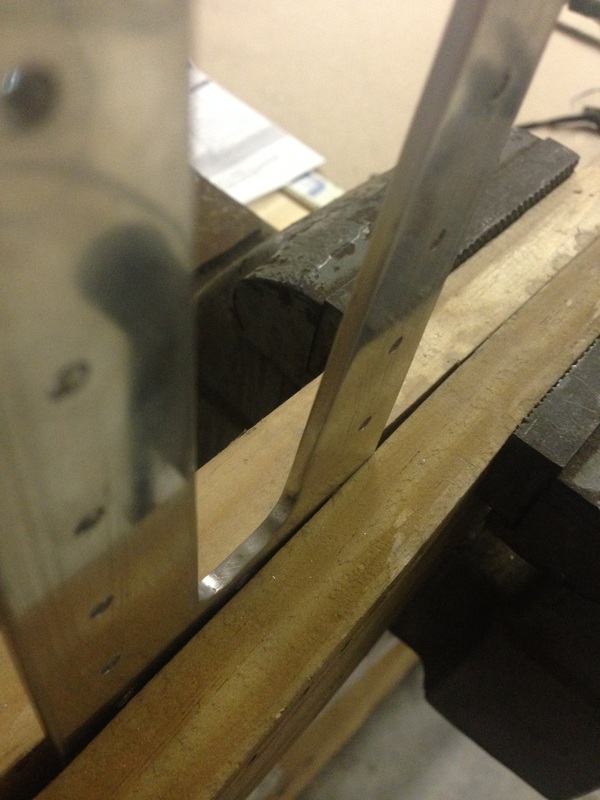
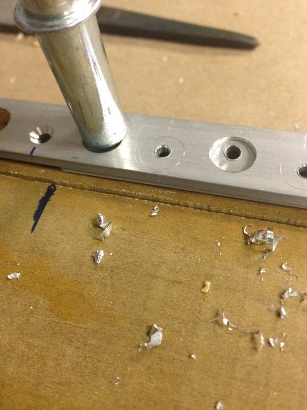
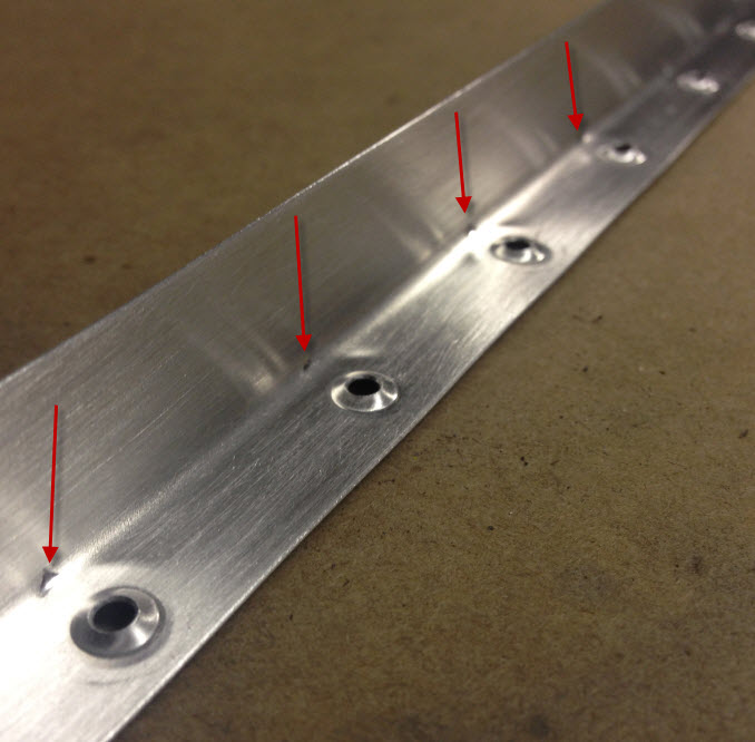
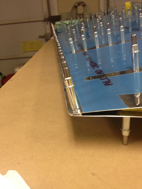
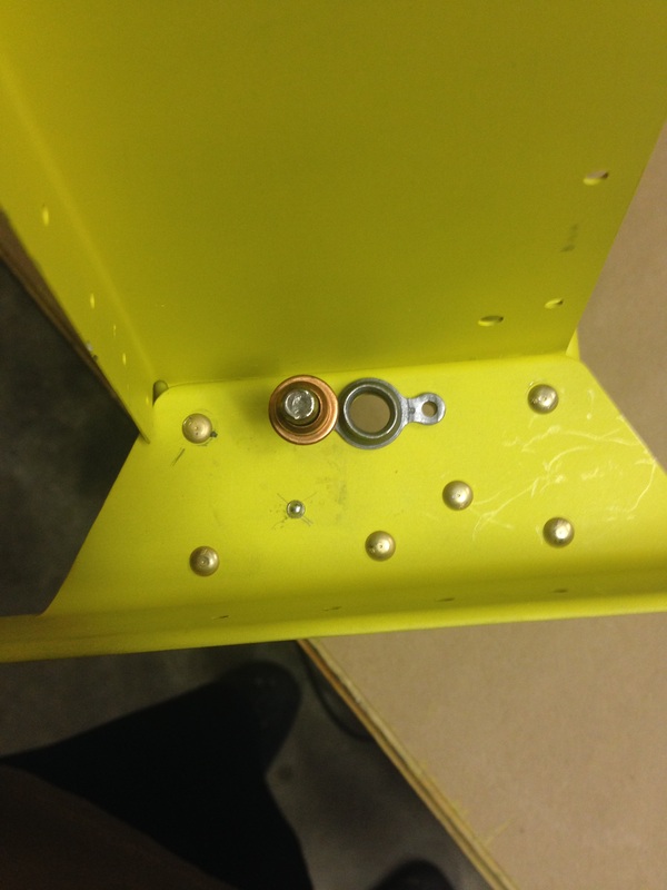
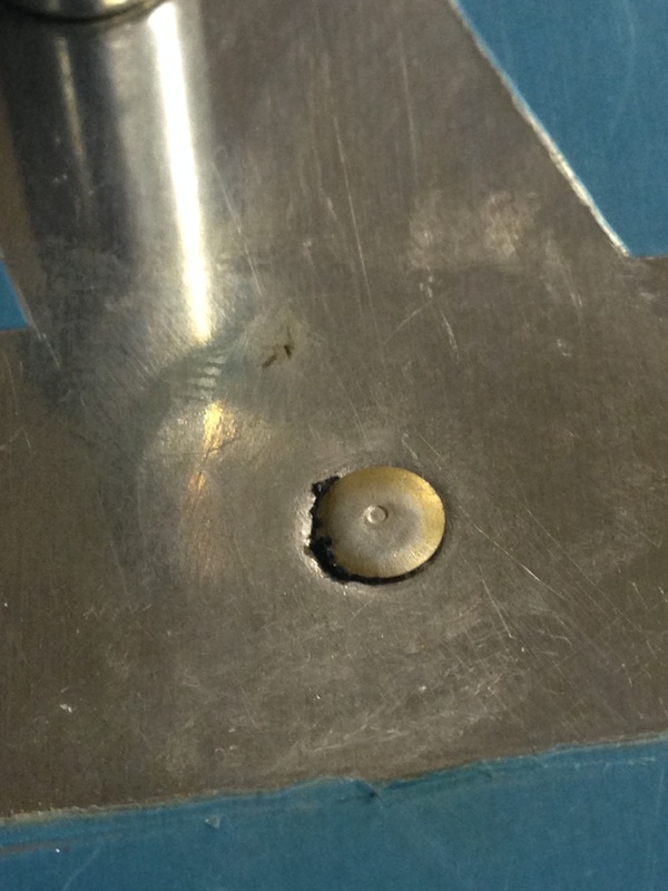
I remembered at the last minute that only the forward hole of the aft two gets a rivet the other hole remains empty. I'm sure it would not hurt if I had done both of them but I've seen several posts on VAF saying the aft most hole was only there to cleco. 
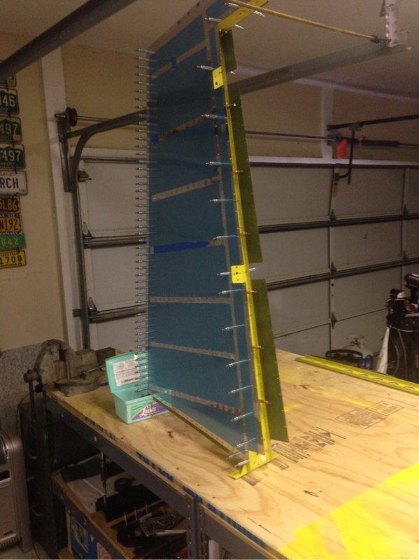
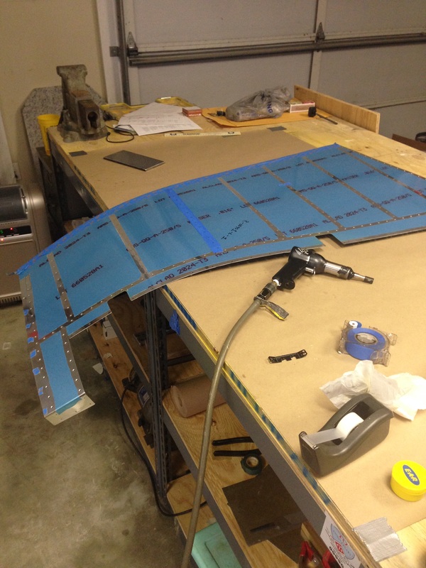
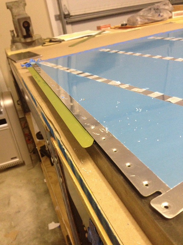
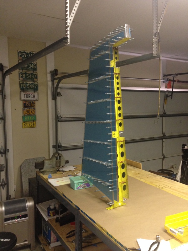
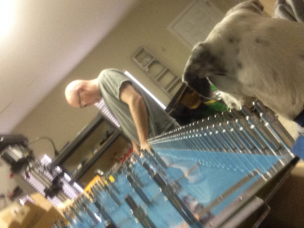
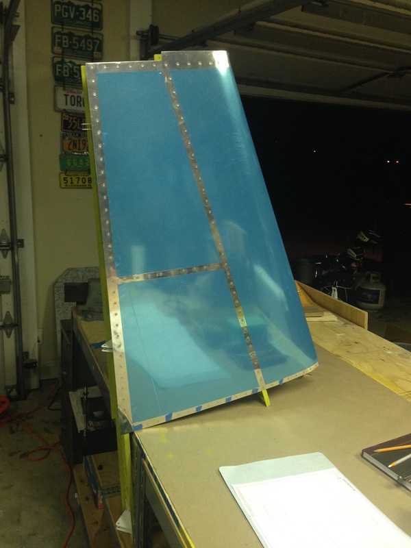
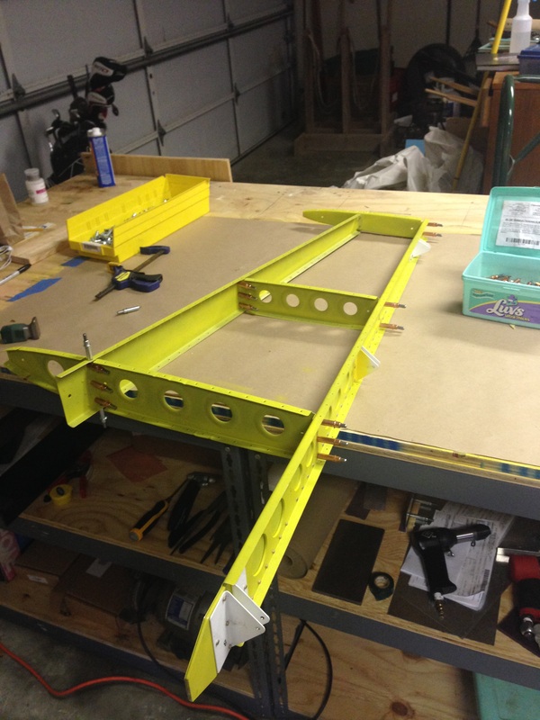
For whatever reason I could not both L and R skins to line up properly when I had the rudder on its side. It's hard to tell in the picture but the bottom side is perfect but clearly the top isn't even close to lining up. 
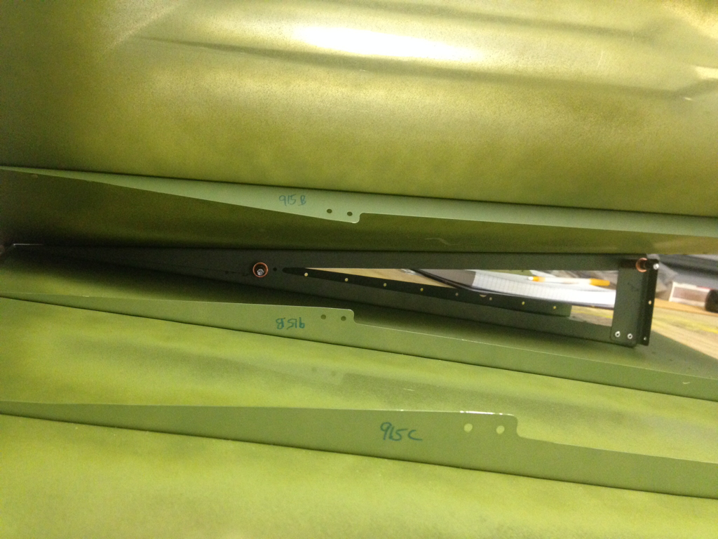
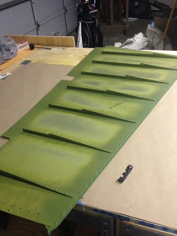
I ended up standing the rudder vertically and magically the skins lined up. I started in the middle of the spar and worked my way back and forth outward until it was all lined up. Next I riveted the shear clips to the spar.
0 Comments
At this point I'm at a stand still with the rudder since I'm still waiting for the replacement horn from Van's. So why not start the horizontal stabilizer? Much like the other couple of sections, the CNC cut parts have extremely rough edge and need alot of attention. The fruits of my labor.
I spent about 4 hours on the trailing edge countersinking both sides. I didn't like my drill press set up so I ended up match drilling the strip to a piece of scrap so the pilot of the CS cutter would have something to guide it. I then took a scrap piece of trailing edge strip and stuck it underneath the piece I was drilling and clecoed the whole sandwich to the scrap. I chucked the CS cage in my cordless drill and proceeded SLOWLY by cutting a little at a time constantly rechecking with a flush rivet. I read on VAF to that you should CS slightly below flush which means going deep enough to see a small ring around the flush rivet. I know the process wasn't the most efficient, but it worked.
Back riveting the rudder stiffeners was pretty straight forward and one of the most enjoyable parts of the build thus far. I forgot to dimple the attach strip and didn't realize it until after I had riveted it to the skin. Oh well, drilling out the few rivets was pretty painless.
While halfway through dimpling the stiffeners I noticed that the female die was leaving a slight mark on the inside edge of the stiffener. I posted the question on VAF whether or not I needed to replace these. The consensus was that where the marks were are not the load bearing part of the stiffener and that I needed to use a reduced diameter female die. I already have the reduced diameter dies but just didn't not think to use them. Chalk it up as another lesson learned! Here is my airplane part christmas tree. I hung the stiffeners from the ladder and had the space heater blowing on them to help accelerate the drying since it has been so humid here.
Here is the entire rudder (sans the horn brace) clecoed together. Now time to take it all apart dimple, prime, etc. In the last picture you can see that Louie decided to take a more active role today and supervise. I am amazed that this dog is un-fazed by the rivet gun, drill, etc. I bet he will be a good flying buddy when its all said and done.
After a few days of deburring and priming parts I was able to start putting them together. Here is the making of an RV-14 rudder. Van's did not include the proper length rivet for the lower nut plate. My friends at the local FBO let me bum a few rivets from the shop. 470AD4-9's were what was necessary to secure these nut plates.
The first steps in the rudder section have you separate and debur ALOT of parts. There aren't many pictures in the early steps due to the monotony of the work. The rudder horn brace on the left was damaged while I was cutting it on the band saw. First parts reorder to Van's! Good News: Part replacement with shipping $12.50. Bad News: Holidays. It took over two weeks before I received the replacement.
I am unhappy with the final rivets on the top VS rib flange. I should have flipped the rivet the other direction so I would not get the flange pucker like I did. The joint is sound but I just don't like the look of it. I have learned my lesson though on fixing something that doesn't need to be fixed!!
I have learned early on if something is cosmetically unsatisfactory but structurally sound, LEAVE IT ALONE!! I had a very light smiley on one of the hinge bracket rivets so I decided I'd replace it. After I got the rivet out a portion of the manufactored head was stuck to the paint/powder coat of the hinge bracket. I used a sharp wood chisel to unembed the rivet head and in the process successfully managed to gouge the surface of the bracket. I polished it it out and contacted Van's and they said it would be fine. Here the internal structure of the vertical stabilizer is all put together. I wasn't very happy with the first flush rivet on the VS skin. I had tape over the rivet set so I wouldn't mar the skin. The result left a slightly "domed" rivet head. Although it was hardly noticeable and one rivet out of many on the skin, I decided to leave it alone since it was in a bad spot. I will take the tape off of all the flush rivet sets from now on.
|
Categories
All
Archives
March 2016
|